

In a common AC induction motor, a magnetic field is induced in the rotor and the power is supplied directly to the stator. The power used to induce the magnetic field in the rotor is commonly known as reactive power since it does not produce work. The power supplied to the stator is best known as active or real power for it produces the torque of the motor. Together, the real and reactive power form the total or apparent power in the system. This is often depicted on a power triangle.
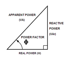
Figure 1: Simple Power Triangle
The displacement power factor can be determined through two ways using the power triangle;
- Active Power / Apparent Power
- Solve for φ (The displacement angle between voltage and current)
In an induction motor the amount of reactive power that is required to generate the rotor’s magnetic field is constant regardless of the load. However, the amount of real power required for an induction motor varies with the load. Therefore, the ratio of real power to apparent power decreases when an induction motor is lightly loaded. This displacement pulls the current out of phase with the voltage, creating a larger φ angle and a resulting lower displacement power factor.
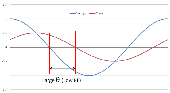
Figure 2: Displacement of a Lightly Loaded Motor without VFDs
When installing a variable frequency drive (VFD) with an induction motor, the voltage and current will remain almost perfectly in phase regardless of its load. The DC bus capacitors within the VFD supply the required reactive current to the motor in order for its rotor to induce a magnetic field. The result is that the AC supply line now only has to supply real power to the drive. This thereby produces a smaller φ angle and a significantly higher displacement power factor.
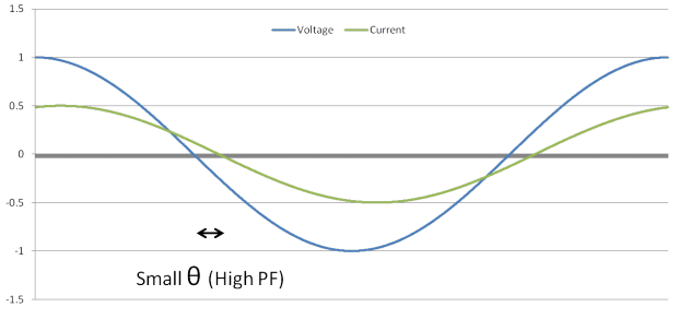
Figure 3: Displacement of an Induction Motor with VFDs
A lightly loaded induction motor will have a VFD input current of nearly zero as the largely reactive current does not flow from the supply side. Since only the “real” current component is returned to the supply side the VFD input current remains in phase with the supply voltage under all loading conditions. Therefore the power factor cos φ equals unity or close to it when VFDs are used.
However this is not the case in environments where measurable harmonics are present as the true power factor of the system takes both the displacement power factor and the total harmonic distortion (THD) into account. A typical full-wave diode bridge rectifier within a VFD has approximately 45% current harmonic distortion. Using the formula in Figure 4 below, an expected 0.99 power factor with 0.45 THD would result in a 0.90 power factor.
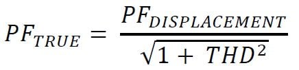
Figure 4: True Power Factor Calculation
There is a drawback in using VFDs specifically due to the significant harmonic current distortion they produce in their operation. The full-wave diode bridge rectifiers within the VFD draw their current over a very short duration at the peak of the voltage wave. This produces an excellent power factor but at the cost of substantial harmonic content, depending on the short circuit current available.
Harmonic currents are reactive as they do not produce useful work and therefore remove some of the power factor benefits that the VFD provides. In order to determine the true power factor of the induction motor it must include the total harmonic distortion (THD) in its evaluation.
To reduce the induced current harmonic distortion it is recommended to install a 3% or 5% line reactor on the input of the VFD. This will lower the harmonics within the system as well as provide protection against nuisance tripping of the drive though line-side voltage transients.
For more information
