


Servo based motion continues to grow as drive technologies become more affordable and easier for motion control programmers to integrate into projects. Some manufacturers have really reduced the ease of implementing servo devices to be extremely close to that of buying an off the shelf robot: Let the software know that you are using a servo drive, give it a real name, let it know the gearing ratio it may have, and what the output distance of that gearing is and you are set. The software configures the rest and tunes the system automatically, leaving the motion programmer with the task of telling the servo system, in machine units (degrees, millimeters, inches), where you would like it to go and how fast, or in some cases, moving the mechanical load to the position and teaching the system. Even replacing a mechanical cam with an electronic cam is easy. Simply get the polar coordinates of the mechanical cam (really easy with CAD software) and export the coordinates into the servo’s cam generator software.
Bottom line, implementing a servo solution isn’t tough. There are some things to consider before you get out and start using servo devices on everything you do.
Why is a servo required?
Just because servos are reducing in price doesn’t mean they are what you need. It may be overkill. A conveyor will do just fine with a normal async motor running off a soft starter or VFD. These solutions are still more affordable and easier to source.
A servo solution should be considered when precision and speed are necessary in the application. Servo drives typically have faster control loops than a VFD, and servomotors are generally cleaner and faster than hydraulic actuation. Servomotors, or synchronous motors, also hold a major one up against asynchronous induction motors when the application is very dynamic. This is because servomotors, for the most part, have a constant torque rating through their entire nominal range of speed, where induction motors have a non-linear torque curve that usually sees nominal torque available only at nominal speed.
Is there an alternative?
There are various alternatives to servomotors. With VFD technology now at its peak, it is not hard to find VFDs that have a position loop. If you need to move a load from point A to point B, and speed is not of huge importance, a VFD paired with an induction motor, encoder, and appropriately sized gearbox will work just fine.
Another actuator to consider is a stepper motor. Typically, these motors move slower than servomotors, however, they have other advantages that are attractive. Steppers bring high torque density, meaning that when compared to a servomotor in terms of dimension and weight, stepper motors far exceed the torque capability of a servo. This makes them ideal for slower applications where high torque is required, such as a setup axis or clamps. Steppers are even used in some low end CNC applications as well. When paired with a stepper drive that has the ability to control in micro steps, it is possible to achieve positional accuracies of 0.05 degrees or less on the motor shaft. Stepper motors generally bring a price advantage over servo motors as well. A word of caution on steppers: they get very hot when being used continuously.
My application needs a servo motor.
If you have decided that your application is best suited for servo motion, you now need to consider the following:
1. What dynamics are involved?
To start off right, you will need to have a firm understanding of everything that will be attached to your servo motor shaft. Drawing a drivetrain diagram to start is the best approach. Make sure to include as much detail as possible, including shaft dimensions and material. Length and rigidity of shaft material plays an important effect on determining how your application will perform. Making sure to note pulley dimensions, drum dimensions, screw pitch, screw diameters and lengths, load masses, etc. is vital to ensuring you select the right servo motor ahead of time.
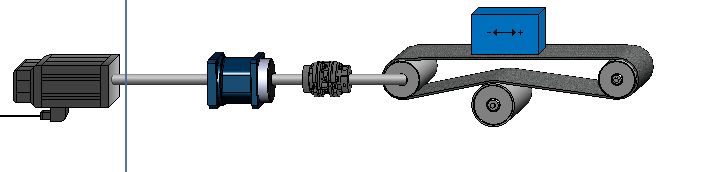 Figure 1: Drivetrain diagram.
2. How accurate and repeatable does the application need to be?
Shaft rigidity, gearbox backlash, holding force between the load and carrying device, and feedback type all come together to effect how accurate and repeatable your system is. In many applications, servo motion accuracy and repeatability is well above the requirements of the application, however, there are some applications where this can present an issue. Make sure to add up all the tolerances each piece of your drivetrain introduces to get the complete picture of what the final accuracy your load will have. If your system has a lot of backlash, torsional deflection, spring, or slip, you may find you will need to have a positional feedback device directly mounted at your load as well as on your servomotor to accurately control the application.
Take this example:
- Servomotor with directly mounted encoder with precision of 120 arcseconds, or ±0.033 degrees of the rotor shaft
- 3:1 Gearbox with maximum backlash of 15 arcminutes, or 0.25 degrees
- Gearbox is connected to a rotary shear using a solid 14 mm steel shaft that is 250 mm long
- For simplicity, the rotary shear requires an applied torque of 25 Nm
So, before we even get to determine shaft deflection in this scenario, the accuracy of the output of the gearbox, starting from rest, can be determined as:
Lagging output accuracy = (-0.033encoder degrees – 0.25backlash degrees) / 3gear ratio = -0.11 degrees
Leading output accuracy = (0.033 encoder degrees + 0 backlash) / 3gear ratio = 0.01 degrees
At the gearbox output, the difference between where the servo drive believes the load is and where the load actually is can be off by -0.11 degrees to 0.01 degrees. Which isn’t much, but something to consider.
Taking shaft deflection into account:
Where
Θ = torsional deflection in radians
L = shaft length (mm)
T = applied torque (N-mm)
G = modulus of rigidity (Mpa)
J = polar moment of inertia (mm4)
For our case
L = 250 mm
T = 25,000 N-mm
Gsteel = 75,550 Mpa
J = 3,771.48 mm4
We end up with a torsional deflection of 0.0219 rad, or 1.25 degrees.
This means the load is lagging the expected position by 1.25 degrees. With the accuracy tolerance calculated with encoder tolerance and gearbox backlash, the actual position of the load could range from -1.36 degrees to -1.24 degrees compared to the position the drive thinks the load is at. If this was a shear that was in sync with a web, and the radius of the shear was 50 mm, the shear could be off expected position on the web by as much as 1.18 mm.
Now this was a completely fictitious scenario with made up values but taking some time to understand your application’s accuracy can help address problems before they happen. In this situation, if the calculated accuracy is not acceptable, implementing a larger shaft would reduce deflection. On some drives, a secondary load encoder can be used to correct positional error. Another option to reduce tolerances introduced by the encoder and gearbox backlash is to get a premium gearbox with a higher gear ratio.
3. Inertia mismatch
Inertia mismatch (IM) is something I find to be the application killer when sizing a system. Consider a situation where there is a need to move a large load at a relatively low speed. I want the load to stop in the right position, quickly, with little to no overshoot. I do a torque calculation and determine that I only need 0.5 Nm of torque, so I head out to find a small motor that can do the task, and everything seems great. If you were to stop your sizing activity at this point, you may find yourself frustrated when you begin to commission the system and find that you are not able to get the motion control specification you aimed for. Not because your motor couldn’t handle it, but because the inertia mismatch was so far off that the drive’s position control loop simply cannot handle the task. Many sources suggest an IM between motor and load should be kept at 10 or below in a servo application. This would mean a 1.30364e-4 kg-m2 load should be paired with a 1.30364e-5 kg-m2 or larger rotor inertia. Having a rotor inertia that is 10 times less than your load inertia would be ridiculous in many applications though, so we rely on gearboxes to provide a mechanical advantage.
In many applications, servomotors can provide the required torque without a gearbox. Adding a gearbox would only reduce the output speed available in our application, while increasing torque output that the application does not need. However, gearboxes reflect the inertia of the load as seen by the rotor by a factor of 1/i2 . So in the case of a motor with rotor inertia of 0.16 kg-cm2 driving a load of 19.2668 kg-cm2, a gearbox with an i = 4 gear ratio would be needed to get the IM into a range below 10:1. This relationship is why so many servomotors come with gearboxes.
As your become more experienced with motion control and what various applications require, and how your selected servo drive performs, you may find that you can get away with IMs that are greater than 10:1. For example, using a servo to move a rotary object at constant speed that has little dynamics, could easily be handled by a system with a 100:1 IM. Using feed forward tuning when available can also help handle scenarios where the IM is larger than 10:1.
4. What electrical supply is available?
Another major consideration when choosing a servomotor, or any motor to that matter, is the available supply voltage.
Servomotors are rated in various ways. Typically, the side of the servomotor has an AC voltage rating on the side. 208 VAC and 460 VAC are common ratings you may see on the side of a servomotor being used in North America. When you go looking for motor information from your motor manufacturer, you may find that they no longer reference AC voltage on their datasheets, but instead move to a DC voltage rating. You may then find yourself asking if you have a PMAC servomotor or is it a brushless DC motor. Most likely if it as an AC rating on the side, and it has been labeled as a servomotor, it will be a servomotor. The DC rating comes from the available DC bus voltage of the drive controlling that servomotor.
Not to get into discussions on how a drive works, we can just say that input AC voltage on a drive determines what the rectified DC bus voltage inside a drive will be. 208 VAC produces a 295 VDC bus. 460 VAC produces 650 VDC bus. 400 VAC produces a 565 VDC bus. The relationship is to multiply the AC voltage by , which will provide the rectified DC bus voltage.
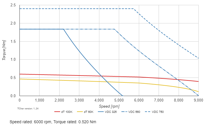 Figure 2: Example of a servo speed-torque curve with various DC bus levels
Enough of the little drive discussion, back to what this means for the servomotor. Servomotors often provide various speed charts based on DC bus voltages. All servomotors have the ability to run on any DC bus voltage up to the manufacturers designated maximum DC bus voltage, which is essentially what the winding insulation is rated for. Operating a servomotor on a DC bus that is less than the nominal DC bus voltage will result in lower speed capability. Increasing the DC bus voltage will also increase speed capability. Torque capacity does not change though! If you were to do a quick estimate on speed change versus DC bus change, you could simply modify speed directly to the percentage change in DC bus voltage. If someone asked me what output speed they could expect for a 3000 RPM motor rated for a 560 VDC bus that was actually going to be on 305 VDC bus, a quick answer would be to estimate around 1500 RPM. For a definite answer, refer to manufacturer torque-speed curves, as seen in Figure 2.
A parting thought I have for you to consider is this: Many servomotors are manufactured and tested for European standards, which includes supply voltage of 400 VAC. This results in a 560 VDC bus. Bring this over to North America where we see 460 VAC, or Canada’s 575 VAC, our DC bus value is higher. This means that servomotors with European ratings perform better with North American power standards. This also helps to shed some light on why North American servomotor data never crosses directly with European servomotor data. We test and rate at different voltages!
IDS is always here to help you figure out what type of motor is best for your application, and what size it should be. Click the button below to contact our sales team to initiate this process.
